



 EN
 RU
Article Summary: An ESS container (Energy Storage System) stores electricity in battery modules and releases it when demand rises, renewable energy production falls, or the grid requires additional power. According to the U.S. Department of Energy (DOE), rechargeable batteries convert electrical energy into chemical energy during charging, and then reverse this process during discharge. A complete containerised ESS combines these battery functions with power conversion, control systems, thermal management and safety equipment to reliably deliver electricity.
What Is an ESS Container?
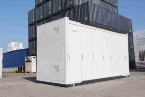
An ESS container is a containerised energy storage system designed to store and supply electrical energy as required. In many commercial and utility-scale projects, it uses a steel enclosure to house battery racks, electrical equipment, control systems, cooling equipment, and safety devices, all integrated in a compact unit in a factory. The term is often used interchangeably with ‘containerised battery energy storage system’ (BESS), particularly when the storage medium is lithium-ion batteries.
Unlike a conventional shipping container, an ESS container is an engineered energy asset, not just a storage enclosure. Its internal layout must accommodate electrical connections, maintenance access, heat removal, environmental protection, and emergency response provisions. Depending on the design, power conversion equipment and transformers may be installed inside the container, in adjacent cabinets, or in separate outdoor enclosures. This configuration allows the system to be adapted for use in applications ranging from solar-plus-storage projects and industrial facilities to microgrids and utility grid support.
The key distinction is that the container provides the physical housing, while the integrated battery and electrical systems perform the energy storage function. Therefore, container dimensions alone do not determine storage capacity or output. Buyers must evaluate battery energy capacity in kilowatt-hours (kWh) or megawatt-hours (MWh), power rating in kilowatts (kW) or megawatts (MW), discharge duration, efficiency, and the operating conditions for which the system is designed.
How Does an ESS Container Work?
An energy storage system (ESS) container receives electrical power, converts it into a form that the batteries can store, and monitors the charging process. It then converts the stored energy back into usable electricity. A typical battery-based system follows a coordinated sequence of charging, energy storage, discharge, and system-level control. The exact arrangement varies according to battery chemistry, grid connection, inverter configuration, and intended application.
Step 1: Electricity enters the system
Electricity can come from the utility grid, a solar photovoltaic installation, a wind farm, a generator, or a combination of sources. Before it reaches the battery cells, the system manages voltage, current, and power flow through its electrical conversion and protection equipment. In a grid-connected installation, the system must also coordinate with the point of interconnection and comply with applicable electrical and grid requirements.
Step 2: Batteries store the energy
During charging, the battery system converts incoming electrical energy into chemical potential energy. In a rechargeable lithium-ion battery, ions move through the electrolyte between the electrodes, while electrons travel through an external electrical circuit. When the system discharges, these electrochemical reactions proceed in the opposite direction, enabling electrical energy to flow out of the battery. The DOE’s battery overview explains this reversible process, as well as why battery cells require an external circuit to charge and deliver electricity.
Battery cells are assembled into modules, which are then grouped into racks or other larger battery assemblies. The number and arrangement of these components determine much of the system’s nominal energy capacity. However, not all of this capacity is necessarily available for use: operating limits, reserve requirements, conversion losses, and the permitted state of charge range of the battery affect how much energy can actually be delivered.
Step 3: The power conversion system regulates electricity
Most battery cells operate on direct current (DC), while commercial facilities and utility grids generally use alternating current (AC). A power conversion system (PCS), commonly based on a bidirectional inverter, converts AC power to DC during charging and DC power to AC during discharge. It also regulates power flow and coordinates electrical behavior with the connected system.
The PCS is not the same as the battery itself. Battery capacity primarily determines how much energy can be stored, while inverter and associated electrical ratings help determine how quickly that energy can be delivered. A system may therefore have a large energy capacity but a comparatively modest power rating, or a high power rating with a shorter discharge duration.
Step 4: The control systems coordinate operation
The battery management system (BMS) monitors operating conditions of the battery, including cell or module voltage, current, and temperature, to ensure that the battery remains within the specified limits. The energy management system (EMS) determines when the energy storage system (ESS) should charge and discharge, according to factors such as operating schedules, electricity prices, renewable generation, site demand, or grid instructions. Depending on the architecture, either a plant controller or a site management system will coordinate the ESS with other equipment and the wider power network.
While these controls work together, they serve different purposes. The BMS focuses on monitoring and protecting the batteries, while the EMS focuses on operating and dispatching the system as a whole. A properly integrated design also coordinates the power conversion system (PCS), alarms, thermal management, communication networks, and emergency shutdown functions.
Step 5: Stored energy is released when required
When the site needs power, the controller issues a discharge command, the battery supplies DC power, and the PCS converts it into AC electricity for the facility or grid. The system can be configured to reduce peak demand, provide backup power where the installation supports it, smooth renewable output, or deliver services such as frequency regulation. Whether an ESS can operate independently during a grid outage depends on its inverter capabilities, protection scheme, transfer arrangements, and system design; grid-connected storage should not automatically be assumed to provide backup power.
What Are the Main Components of an ESS Container?
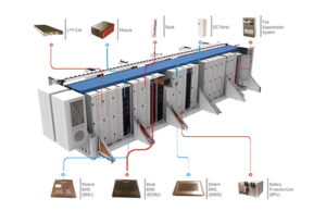
An ESS container is a coordinated system rather than a collection of batteries placed inside a metal enclosure. Its performance depends on the compatibility of its storage, electrical, control, cooling, and protection components. The U.S. Department of Energy’s An Introduction to Energy Storage identifies battery storage, the BMS, PCS, EMS, site management, and balance-of-system equipment as distinct elements of a battery energy storage installation.
Component | Main function | Why it matters |
Battery cells, modules, and racks | Store and release energy electrochemically | Determine much of the system’s energy capacity and operating limits |
Battery management system (BMS) | Monitor battery voltage, current, temperature, and other operating data | Help maintain safe battery operation and identifies abnormal conditions |
Power conversion system (PCS) | Convert power between AC and DC and regulates power flow | Determine important aspects of power delivery and grid interaction |
Energy management system (EMS) | Schedule and coordinates charging and discharging | Align energy use with site demand, renewable output, or grid signals |
| Thermal management | Control battery temperature through cooling or heating as required | Support performance, service life, and stable operation |
| Electrical protection and switchgear | Provides switching, isolation, and fault protection | Help disconnect equipment safely when abnormal electrical conditions occur |
| Fire and gas safety equipment | Detect specified hazards and activates designed mitigation measures | Help manage fire, gas accumulation, and emergency risks |
| Container and auxiliary systems | Protect equipment and provide access, wiring routes, lighting, ventilation, and monitoring interfaces. | Support outdoor installation, maintenance, and system integration |
The enclosure itself must be designed for the environment in which the ESS will operate. Outdoor installations may face rain, dust, solar heat gain, salt-laden air, or wide temperature fluctuations, so enclosure protection, corrosion resistance, thermal design, and cable entry details require careful consideration. A shipping-container appearance does not guarantee that a unit has the environmental protection or electrical safety provisions required for a particular site.
How Does an ESS Container Manage Temperature and Safety?
Temperature control is fundamental to battery operation. Battery cells generate heat during charging and discharging, and excessive or uneven temperatures can accelerate degradation or cause a cell to exceed its permitted operating range. Depending on the battery chemistry, system density, climate, and manufacturer’s design, an ESS container may use liquid cooling, forced-air cooling, or another engineered thermal-management arrangement. Some systems also provide heating for cold conditions. Therefore, cooling equipment is part of the operating system, not merely an optional comfort feature.
Safety requires multiple layers of protection because no single sensor or control system can eliminate every battery hazard. The BMS monitors battery conditions and can request reduced power, isolation, or shutdown when defined limits are exceeded. Other protection layers may include temperature and smoke detection, gas detection where appropriate, ventilation, emergency isolation, fire protection, pressure-relief or explosion-mitigation measures, and remote alarms. The exact equipment and its activation logic must be based on system design, hazard analysis, applicable codes and local authority requirements.
The National Fire Protection Association’s NFPA 855 Standard for the Installation of Stationary Energy Storage Systems addresses installation safety considerations, including fire protection, detection, ventilation and explosion control. The relevant edition and local adoption requirements must be confirmed for each project, as compliance cannot be inferred from a product description alone.
In Singapore, for instance, the Fire Code of the Singapore Civil Defence Force includes specific requirements for applicable Emergency Support Systems (ESS) installations, such as battery monitoring, emergency isolation and provisions for fire and gas hazards. The precise requirements depend on the type of installation and the applicable thresholds.
Project owners should request evidence of the complete system’s safety design rather than relying solely on battery-cell certification or general statements that the product is ‘fireproof’. Useful documentation may include product listings, test reports, installation manuals, emergency response procedures, and descriptions of how the BMS, thermal management, detection, and shutdown functions interact. A site-specific review should also address issues such as spacing, access for emergency responders, ventilation discharge locations, and separation from nearby equipment or buildings.
What Determines ESS Container Capacity and Output?
Two specifications are especially important: energy capacity and power rating. Energy capacity describes how much energy the system can store, usually in kWh or MWh; power rating describes how much power it can supply or absorb at a given moment, usually in kW or MW. These figures answer different questions. A 1 MWh system does not necessarily deliver 1 MW for one hour under all conditions, because usable capacity, conversion losses, operating reserves, temperature, and power limits influence actual performance.
A simplified estimate of discharge duration is:
Discharge duration (hours) ≈ Usable energy (MWh) / Output power (MW)
For example, if a system has 4 MWh of usable energy and delivers 1 MW continuously, its idealized discharge duration is approximately four hours. In practice, the delivered duration may be shorter because of conversion losses, auxiliary consumption, reserve settings, and operating limits. This calculation is useful for initial comparisons, but a project specification should distinguish nominal energy, usable energy, AC-deliverable energy, and any guaranteed performance at the point of interconnection.
Specification | What it tells you | Key question for buyers |
Rated energy capacity (kWh/MWh) | Nominal amount of stored energy | Is this nominal capacity or usable capacity? |
Rated power (kW/MW) | Maximum specified charge or discharge power | Is the rating continuous, short-term, or dependent on conditions? |
Discharge duration | How long the system can deliver a specified power level | What energy remains available at the required output? |
| Round-trip efficiency | How much energy is recovered relative to the energy used to charge the system | Is the figure measured on the DC side or AC side, and under what conditions? |
| Depth of discharge and state-of-charge limits | How much of the battery’s capacity can be used in normal operation | What operating window does the warranty allow? |
| Auxiliary power consumption | Electricity used by cooling, controls, pumps, and other equipment | How much net energy is available after auxiliary loads? |
| Degradation and cycle life | How performance may change over time and use | What capacity retention is warranted after a defined period or throughput? |
| Environmental operating range | Conditions under which the system is designed to function | Does the site climate require additional cooling, heating, or protection? |
When comparing proposals, ensure that quoted figures use the same measurement basis. A supplier may quote DC battery energy, while another reports AC energy delivered at the grid connection; these values are not directly interchangeable. Ask for performance guarantees, test conditions, degradation assumptions, and warranty exclusions before using headline capacity or efficiency figures to estimate project economics.
Where Are ESS Containers Used?
Thanks to its modular format, an ESS container is ideal for installations requiring substantial storage capacity, eliminating the need for a dedicated indoor battery room. However, its value depends on the operational problem it is intended to solve. For example, a system designed to support a solar farm may have a different dispatch profile, grid interface, and discharge duration than one installed at a factory to manage peak electricity demand.
Common applications include:
- Renewable energy integration. Solar and wind generation fluctuate with weather and time of day. An ESS container can store surplus electricity and release it later, helping shift energy production toward periods of higher demand and reduce short-term output variability.
- Commercial and industrial energy management. Factories, warehouses, and commercial buildings may use storage to reduce peak demand, support selected critical loads, or improve how on-site renewable generation is consumed. The financial value depends on the local tariff structure, demand charges, load profile, and charging strategy.
- Utility grid services. Utility-scale systems can respond to dispatch instructions and provide services such as frequency regulation, ramp-rate control, and other forms of grid support where the equipment and market rules permit. Their actual contribution depends on inverter capability, control response, interconnection requirements, and available energy.
- Microgrids and remote power systems. An ESS container can coordinate with renewable generation and generators to balance supply and demand. Islanded operation and backup capability require appropriate controls, protection, and system architecture; they are not guaranteed by the presence of batteries alone.
- Charging infrastructure and distributed energy projects. Storage can help manage concentrated loads from electric-vehicle charging or other equipment with high, time-varying power demand. Project designers must account for charging schedules, required output, available grid capacity, and the economics of battery cycling.
Across these applications, the ESS container serves as a flexible component within a larger energy system. It does not generate primary energy like a solar array or generator; it shifts energy across time and manages how electricity is delivered. This distinction matters when estimating project savings, because storage economics depend on both the energy it receives and the value of the energy or services it provides later.
How to Choose the Right ESS Container?
Selecting an ESS container starts with the use case, not the enclosure size. A project intended for two-hour peak shaving may require a different power-to-energy ratio from a renewable energy project that needs longer discharge periods. Buyers should define the required power, usable energy, daily operating pattern, expected annual throughput, environmental conditions, and required service life before comparing equipment.
A practical evaluation process includes the following steps:
- Define the load or grid requirement. Establish the power level, required duration, response time, and whether the system must operate during grid outages. Identify whether the application is primarily energy shifting, peak reduction, renewable integration, or grid services.
- Compare usable capacity and system efficiency. Check whether each proposal states DC or AC energy, nominal or usable capacity, and whether efficiency includes auxiliary loads. Use consistent measurement boundaries to avoid misleading comparisons.
- Review the integration architecture. Confirm whether the PCS, transformer, switchgear, EMS, cooling system, and communications equipment are included in the scope of supply or must be purchased separately. Unclear boundaries can create commissioning delays and disputes over responsibility.
- Evaluate safety and environmental suitability. Review battery chemistry, operating-temperature limits, enclosure protection, detection and mitigation systems, required clearances, and local permitting obligations. Request relevant technical documentation and confirm that the proposed configuration is appropriate for the intended installation.
- Assess lifecycle cost and support. Consider more than just the initial purchase price. Warranty conditions, capacity retention, maintenance requirements, replacement strategy, software support, spare parts, and expected auxiliary consumption all influence the total cost of ownership.
In our view, selecting the optimal containerised energy storage solution also necessitates evaluating the physical enclosure and logistics equipment against the project’s installation and integration requirements. Please consult our CIMC TLC|RYC|XLC for information on relevant containers and logistics equipment, and confirm the ESS-specific structural, electrical, thermal and safety requirements with the responsible system integrator. Do not assume that a container suitable for one purpose meets the requirements of a battery installation without the necessary engineering verification.
Frequently Asked Questions About ESS Containers
- What does ESS stand for in an ESS container?
ESS stands for Energy Storage System, which stores energy for use at a later time. In containerized battery applications, it typically refers to a packaged system combining batteries, power electronics, controls, and supporting equipment.
- How does an ESS container store electricity?
A battery-based ESS container stores energy by converting incoming electricity into chemical energy inside rechargeable battery cells. During discharge, the cells convert that stored chemical energy back into electrical energy for a connected load or grid.
- What is the difference between an ESS container and a BESS container?
ESS is a broad term for an energy storage system, while BESS specifically means Battery Energy Storage System. In many containerized projects, the terms are used interchangeably because batteries are the primary storage technology.
- How long can an ESS container supply power?
Its discharge duration depends on usable energy capacity and the power being delivered. A system with 2 MWh of usable energy could theoretically deliver 1 MW for about two hours, although actual performance depends on losses, operating limits, and auxiliary consumption.
- Are ESS containers safe for outdoor installation?
They can be designed for outdoor installation when the enclosure, electrical equipment, thermal management, and safety systems are suitable for the site. Installation must also meet applicable codes, fire-safety requirements, separation distances, and manufacturer instructions.
- What is the difference between ESS container capacity and power rating?
Capacity, measured in kWh or MWh, indicates how much energy the system can store, while power, measured in kW or MW, indicates how quickly it can deliver or absorb electricity. Both specifications are needed to determine whether a system can meet a project’s load and discharge-duration requirements.
Conclusion
An energy storage system (ESS) container stores electricity in rechargeable batteries and releases it through a coordinated system of power conversion, battery monitoring, energy management, thermal control, and safety equipment. Its effectiveness depends on various factors, including battery capacity, usable energy, power rating, efficiency, environmental conditions, integration quality, and the requirements of the installation site.
The most reliable approach for project developers and equipment buyers is to first define the intended application, then compare technical specifications consistently and verify that the complete system meets applicable safety and grid requirements. Treating the ESS container as an integrated energy asset, rather than simply a container filled with batteries, provides a more useful foundation for equipment selection, project planning, and long-term operating performance.