



 EN
 RU
Quick Answer:
An ESS container(Energy Storage Container) is a factory-assembled, self-contained enclosure that houses battery modules, power conversion systems, thermal management units, and safety controls. These components work together to store electrical energy and discharge it on demand. This enables grid stabilisation, renewable energy integration, and backup power supply without the need for purpose-built civil infrastructure at the deployment site.
According to the Handbook of Energy Storage: Demand, Technologies, Integration (eds. Sterner & Stadler, Springer, 2019), and the International Electrotechnical Commission standard IEC 62933-1:2018 (Electrical Energy Storage Systems — Part 1: Vocabulary), containerised energy storage systems are the most common commercial configuration for utility-scale and industrial stationary storage deployments worldwide. They offer standardised interfaces, pre-commissioned subsystems and transportable form factors, which dramatically reduce project development timelines compared to custom-built battery rooms. According to BloombergNEF’s Energy Storage Market Outlook 2024, global ESS container capacity additions exceeded 42 GWh in 2023 alone, underscoring the technology’s central role in the accelerating energy transition.
Introduction
The global energy landscape is undergoing a structural transformation, driven by the rapid expansion of intermittent renewable energy sources such as solar photovoltaics and wind power. The variability of these sources imposes increasingly complex balancing demands on transmission and distribution grids that were designed for predictable, dispatchable energy generation. The ESS container is a practical, deployable solution that addresses this transformation. It is a modular, pre-integrated energy storage unit that packages decades of advances in battery technology, power electronics, and thermal engineering into a standardised enclosure. It can be transported on a standard flatbed truck, positioned on a prepared concrete pad and connected to the grid or a behind-the-meter electrical system within days, rather than the months or years demanded by conventional energy infrastructure development.
The term ‘ESS container’ is used across the utility, commercial, industrial, and microgrid market segments to describe systems ranging in capacity from 250 kWh containerised units for commercial building backup applications, to multi-megawatt-hour installations comprising dozens of interconnected containers that deliver frequency regulation, peak shaving, transmission congestion relief, and renewable energy firming services to grid operators and large industrial consumers. Regardless of scale, the defining characteristic of an ESS container is its integration philosophy: all critical subsystems are engineered, assembled, tested, and commissioned in a factory environment before shipping, which radically reduces field installation complexity and enables repeatable, predictable performance across diverse deployment geographies. This article provides a comprehensive technical and commercial overview of what an ESS container is, how it works, what it contains, and how it is deployed, and is structured to support engineering procurement decisions and strategic energy planning.
What Is an ESS Container? Core Definition
An energy storage system (ESS) container is a standardised, weatherproof enclosure, typically based on ISO 20-foot or 40-foot shipping container dimensions, although custom sizes are available. It houses a complete energy storage system comprising battery cells, battery management electronics, power conversion hardware, thermal management infrastructure, fire detection and suppression systems, and communication and control interfaces. The system stores electrical energy electrochemically in battery cells and delivers it to a connected electrical network via a power conversion system (PCS), which manages the conversion between the DC voltage of the battery bank and the AC voltage of the grid or load.
The containerised format became the dominant commercial form factor for large-scale battery energy storage in the early 2010s. This was driven by the convergence of rapidly declining lithium-ion battery costs and the standardisation of ISO container logistics infrastructure. It also reflected the practical recognition that utility and industrial customers required energy storage solutions that could be deployed quickly, without the regulatory delays, construction costs, and long lead times associated with permanent electrical infrastructure projects. By adopting the ISO container as the physical platform, ESS manufacturers were able to leverage an existing global supply chain for structural fabrication, logistics, and field positioning, enabling projects in remote industrial sites, island grids, and locations in developing markets that would have been uneconomical with custom-built infrastructure approaches.
The lithium iron phosphate (LFP) chemistry has become the dominant cell technology in ESS containers for stationary applications, valued for its thermal stability, long cycle life — typically 4,000–6,000 full charge-discharge cycles to 80% capacity retention — and competitive energy density at the system level. Nickel manganese cobalt (NMC) chemistries remain relevant in applications where energy density is premium-constrained, while emerging sodium-ion and solid-state technologies are beginning to appear in pilot ESS container deployments targeting longer-duration applications.
Key Components Inside an ESS Container
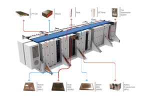
In order to evaluate system performance specifications, maintenance requirements, and integration complexity, it is essential to understand what physically exists inside an ESS container. A fully integrated ESS container comprises six major subsystem categories, each of which performs a distinct and essential function within the overall energy storage system architecture.
Battery modules and racks form the electrochemical core of the container. Individual lithium-ion cells — which can be cylindrical, prismatic, or in a pouch format, depending on the manufacturer’s selection — are assembled into modules that manage cell interconnection, local temperature monitoring, and cell balancing. These modules are mounted in vertical racks within the container, and the configuration of these racks is determined by the target energy capacity of the system and the nominal voltage and capacity specifications of the cells. A typical 40-foot ESS container using LFP prismatic cells may house 16–24 battery racks, providing a total system energy capacity of between 2.5 and 5 MWh, depending on the energy density of the cells and the design of the pack.
Power Conversion System (PCS) is the power electronics subsystem responsible for converting DC energy from the battery bank into grid-frequency AC power (and vice versa during charging). The PCS in an ESS container is typically a multi-quadrant, bidirectional inverter-charger capable of operating in grid-following mode (following grid voltage and frequency) or grid-forming mode (establishing voltage and frequency reference in islanded microgrids). PCS power ratings in commercial ESS containers range from 250 kW to 1,500 kW per container unit, with multiple containers paralleled to achieve project-level power targets.
Thermal Management System (TMS) maintains battery cell temperatures within the optimal operating window — typically 15°C to 35°C for LFP cells — using precision air conditioning, liquid cooling (direct or indirect), or hybrid cooling architectures. Thermal management is the single most significant determinant of battery cycle life in field deployments; cells operated chronically above their optimal temperature range experience accelerated capacity degradation that can reduce system life by 30–50% relative to thermally well-managed peers operating identical charge-discharge profiles.
Fire Detection and Suppression System (FDSS) provides multi-layer protection against thermal runaway events — the primary safety hazard in lithium-ion battery systems. Modern ESS containers employ gas-phase detectors (sensing hydrogen and carbon monoxide released in early-stage thermal runaway) combined with addressable smoke detection and automatic clean-agent or aerosol-based suppression systems that can extinguish a cell-level thermal event before it propagates to adjacent modules. Compliance with standards such as NFPA 855 (Standard for the Installation of Stationary Energy Storage Systems) and FM Global Property Loss Prevention Data Sheet 5-33 is mandatory for insurance qualification in most markets.
Energy Management System (EMS) and Communications provide the supervisory control layer that translates high-level operational commands — from a grid operator, building energy management system, or renewable plant controller — into real-time charge/discharge dispatch instructions for the PCS and BMS. Modern EMS platforms support Modbus TCP/IP, DNP3, IEC 61850, and MQTT protocols, enabling integration with SCADA systems, utility control centres, and cloud-based monitoring platforms with standardized data exchange.
ESS Container Types and Configuration Options
The ESS container market encompasses several distinct product categories differentiated by capacity range, application focus, integration architecture, and form factor. Selecting the appropriate container type requires matching the system’s power and energy specifications to the application’s dispatch requirements, site constraints, and grid interconnection context.
Standard Utility-Scale ESS Containers are 20-foot or 40-foot ISO form factor units designed for high-throughput grid applications including frequency regulation, capacity firming, transmission and distribution (T&D) deferral, and bulk energy arbitrage. These units are designed for outdoor installation in large arrays — a 100 MWh project may deploy 25–40 container units — and emphasize high cycle life, remote monitoring capability, and standardized electrical interfaces that simplify large-array integration. Battery technology is predominantly LFP with liquid cooling, PCS power ratings typically 1–1.5 MW per container, and system round-trip efficiency of 86–92% AC-to-AC at the container level.
C&I Behind-the-Meter ESS Containers target commercial and industrial facilities seeking peak demand charge reduction, backup power continuity, solar self-consumption maximization, or participation in demand response programs. These systems are typically smaller (250 kWh–2 MWh per container), may include integrated EV charging interfaces or solar inverter coupling, and are designed for installation in urban or campus environments with tighter space constraints and stricter noise and aesthetic requirements than utility-scale sites.
Microgrid and Off-Grid ESS Containers are configured specifically for islanded operation, incorporating grid-forming PCS capability, extended reserve capacity, and fuel-cell or genset integration interfaces. These systems are deployed in remote mining operations, island communities, military forward operating bases, and developing-market rural electrification projects where grid connectivity is absent or unreliable. System autonomy periods of 4–12 hours at full load are typical design targets for these applications.
Long-Duration Energy Storage (LDES) Containers represent an emerging category using iron-air, vanadium redox flow, or compressed air technologies to deliver 8–100+ hour discharge durations that lithium-ion chemistry cannot economically support. While still a small fraction of total ESS container deployments by volume, LDES containers are attracting significant project development interest for seasonal storage, transmission congestion relief, and long-duration backup applications that require fundamentally different duration-to-power ratios than lithium-ion systems are optimised to deliver.
Utility-Scale Grid | 2.5–5 MWh per unit | Frequency reg., T&D deferral, arbitrage | LFP (liquid-cooled) | 1–4 hours |
C&I Behind-the-Meter | 250 kWh–2 MWh | Peak shaving, backup, solar + storage | LFP or NMC | 2–6 hours |
Microgrid / Off-Grid | 500 kWh–5 MWh | Island power, remote electrification | LFP (air or liquid) | 4–12 hours |
| Long-Duration (LDES) | 1–20 MWh | Seasonal storage, multi-day backup | Vanadium flow, Fe-air | 8–100+ hours |
| Industrial UPS / Backup | 100–500 kWh | Critical facility continuity | LFP or NMC | 30 min–4 hours |
How Does an ESS Container Work? System-Level Operation
The operational logic of an ESS container follows a charge-store-dispatch cycle governed by the EMS in response to external signals from grid operators, building automation systems, or pre-programmed dispatch schedules. During a charging cycle, the PCS draws AC power from the grid or from co-located renewable generation, converts it to DC at the battery bank’s operating voltage (typically 600–1,500 VDC for utility-scale systems), and delivers it to the battery racks under BMS supervision that ensures no individual cell exceeds its maximum charge voltage or temperature limits. The TMS actively manages cell temperatures throughout the charging process, increasing cooling capacity during high-power charge events that generate significant heat at the cell and module level.
During a discharge cycle, the process reverses: the BMS signals the PCS to draw DC current from the battery bank at the rate required to meet the dispatch power target, and the PCS converts this DC power to grid-quality AC at the specified voltage and frequency. Modern PCS platforms can execute ramp rates of 1 MW per second or faster, enabling the ESS container to respond to grid frequency deviations within 200–400 milliseconds — a response speed that no conventional generation asset can match and that makes fast-frequency regulation one of the most commercially attractive applications for ESS containers in liberalized electricity markets.
The EMS orchestrates this charge-discharge cycle in real time, continuously optimizing the system’s operating state against multiple simultaneous objectives: maintaining state of charge within the operator-specified operating window (typically 10–90% SoC to preserve cycle life), responding to dispatch commands from the grid operator or building EMS, minimizing battery degradation by avoiding extreme SoC levels and high-temperature operation, and logging operational data to cloud-based platforms that enable performance verification, warranty compliance monitoring, and predictive maintenance scheduling.
Real-world Application Case Study: Commercial Solar + Storage Projects
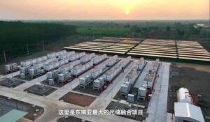
One of the most inspiring deployment examples for understanding the practical value of containerized Energy Storage Systems (ESS) is the growing number of solar + storage projects serving commercial and industrial facilities in Thailand. In these regions, grid reliability is challenging, and daytime solar radiation is high, making the co-location of battery storage systems with rooftop or ground-mounted photovoltaic systems extremely cost-effective. This project perfectly demonstrates the performance and economic benefits of a well-designed containerized energy storage system deployment in such environments.
When selecting a containerized energy storage system (ESS) solution for such projects, we highly recommend our CIMC TLC|RYC|XLC solution. Our containerized energy storage system product line boasts proven field performance data, comprehensive building management system (BMS) and energy management system (EMS) integration capabilities, and a robust after-sales service system—advantages that are crucial for projects where long-term operational support is as important as system specifications.
Industry Standards and Safety Certifications
The ESS container industry is governed by an expanding framework of international and regional standards that address system safety, performance testing, grid interconnection, fire protection, and installation requirements. Compliance with these standards is not merely a commercial best practice — it is a prerequisite for project insurance qualification, utility interconnection approval, and regulatory permitting in most major energy storage markets.
IEC 62933 is the primary international standard series for electrical energy storage systems, covering terminology (Part 1), unit parameters and testing methods (Part 2), planning and performance assessment of grid-integrated systems (Part 3), and guidance on environmental aspects (Part 5). IEC 62933-2-1 and IEC 62933-2-2 define the test methods used to verify ESS container performance specifications — capacity, round-trip efficiency, response time, and self-discharge rate — providing a standardized basis for comparing manufacturer specifications across products.
UL 9540 (Standard for Energy Storage Systems and Equipment) and UL 9540A (Test Method for Evaluating Thermal Runaway Fire Propagation in Battery Energy Storage Systems) are the dominant North American safety standards, required by the National Electrical Code (NEC) and adopted as reference standards by NFPA 855. UL 9540A testing — which subjects a single cell to thermal runaway initiation and measures whether the event propagates through the module, rack, and unit — has become a de facto global standard for ESS container fire safety qualification, required by insurers and adopted by fire authorities in Europe, Australia, and Asia-Pacific markets beyond its US origination.
IEEE 1547-2018 governs the interconnection and interoperability requirements for distributed energy resources — including ESS containers — connected to electric power systems, specifying voltage and frequency ride-through requirements, reactive power capability, and anti-islanding protection that ESS containers must satisfy for grid interconnection approval in US markets. The European equivalent, EN 50549, and the Australian standard AS 4777, provide analogous requirements in their respective jurisdictions, collectively establishing a global framework for ESS container grid interconnection compliance.
Frequently Asked Questions
Q1: What does ESS stand for in ESS container?
ESS stands for Energy Storage System. An ESS container is therefore a self-contained, containerized Energy Storage System — a factory-integrated unit combining battery modules, power conversion electronics, thermal management, and safety systems in a standardized enclosure that can be transported and deployed at a site without requiring custom-built electrical infrastructure.
Q2: How long does an ESS container last?
The operational lifespan of an ESS container is primarily determined by battery cycle life and calendar aging. Most commercial ESS containers using LFP battery chemistry carry performance warranties of 4,000–6,000 full charge-discharge cycles to 80% of rated capacity retention, which translates to a functional battery life of 10–15 years at one cycle per day. The structural enclosure, PCS, and thermal management hardware typically have longer design lives of 20+ years, meaning battery module replacement mid-project-life is often economically viable.
Q3: What is the typical capacity of an ESS container?
ESS container capacities span a wide range depending on container size and battery technology. A standard 20-foot ESS container using LFP battery modules typically offers 500 kWh to 1.5 MWh of usable energy capacity, while a 40-foot container of the same technology may deliver 2.5 MWh to 5 MWh. C&I-focused smaller units start from approximately 100–250 kWh, and utility-scale platforms at the high end of the market offer up to 6–8 MWh per 40-foot container through high-density cell integration.
Q4: What is the difference between an ESS container and a battery cabinet?
A battery cabinet is a rack-mounted assembly of battery modules — typically used indoors in existing electrical rooms — that stores only the battery cells and local BMS hardware, requiring separately installed PCS, thermal management, and fire suppression equipment. An ESS container integrates all these subsystems in a single, weatherproof outdoor-rated enclosure that is factory-assembled and tested before shipment, offering a complete, standalone energy storage solution without requiring a dedicated building or electrical room at the deployment site.
Q5: How is an ESS container connected to the grid? An ESS container connects to the electrical grid through its integrated PCS, which provides the AC power output interface at the specified grid voltage — commonly 400V, 690V, or medium-voltage (10–35 kV) depending on the PCS configuration and grid interconnection requirements. The container’s AC output connects to a transformer (for medium-voltage grid connection) or directly to a low-voltage switchboard, with protection relaying, metering, and grid-code-compliant ride-through and anti-islanding functions managed within the PCS and EMS. Communication to the grid operator or utility control system is established via DNP3, IEC 61850, or Modbus TCP/IP over fibre or cellular data connections.
Q6: Is an ESS container safe for outdoor installation?
Yes — ESS containers are specifically engineered for permanent outdoor installation in a wide range of environmental conditions. The structural enclosure provides weatherproof protection to an IP54 or IP55 rating (protection against dust ingress and water spray), with HVAC and thermal management systems maintaining internal conditions within the battery’s specified operating range regardless of ambient temperature extremes from -30°C to +55°C in most commercial products. Multi-layer fire detection and suppression systems, combined with compliance with NFPA 855, UL 9540A, and applicable local fire codes, ensure that the fire safety risk profile of an outdoor ESS container installation is compatible with industrial, commercial, and utility site safety requirements.
Conclusion
The ESS container has evolved from a practical logistics solution, leveraging the standardised dimensions of ISO containers and the global transport infrastructure, into the defining product format of the modern stationary energy storage industry. It enables grid operators, industrial energy consumers and microgrid developers to deploy technically sophisticated, high-performance energy storage systems with unmatched speed, cost predictability and site flexibility. With battery cell costs continuing to decline in the long term, grid codes in major markets increasingly mandating storage co-location with renewable generation assets and industrial and commercial energy consumers facing growing pressure to reduce peak demand expenditure and improve energy resilience, demand for ESS container solutions will continue to expand rapidly across every energy market segment and geography. Engineers, project developers, and energy managers evaluating energy storage options must understand the technical architecture, application context, and standards framework of the ESS container to make informed procurement, integration, and operational decisions.
References:
- Sterner, M. & Stadler, I. (Eds.). Handbook of Energy Storage: Demand, Technologies, Integration. Springer, 2019.
- IEC 62933-1:2018. Electrical Energy Storage Systems — Part 1: Vocabulary. International Electrotechnical Commission.
- IEC 62933-2-1:2021. Electrical Energy Storage Systems — Part 2-1: Unit Parameters and Testing Methods — General Specification. IEC.
- BloombergNEF. Energy Storage Market Outlook 2024. BloombergNEF, 2024.
- NFPA 855:2023. Standard for the Installation of Stationary Energy Storage Systems. National Fire Protection Association.
- UL 9540:2020. Standard for Energy Storage Systems and Equipment. Underwriters Laboratories.
- UL 9540A:2023. Test Method for Evaluating Thermal Runaway Fire Propagation in Battery Energy Storage Systems and Equipment. Underwriters Laboratories.
- IEEE 1547-2018. Standard for Interconnection and Interoperability of Distributed Energy Resources with Associated Electric Power Systems Interfaces. IEEE.