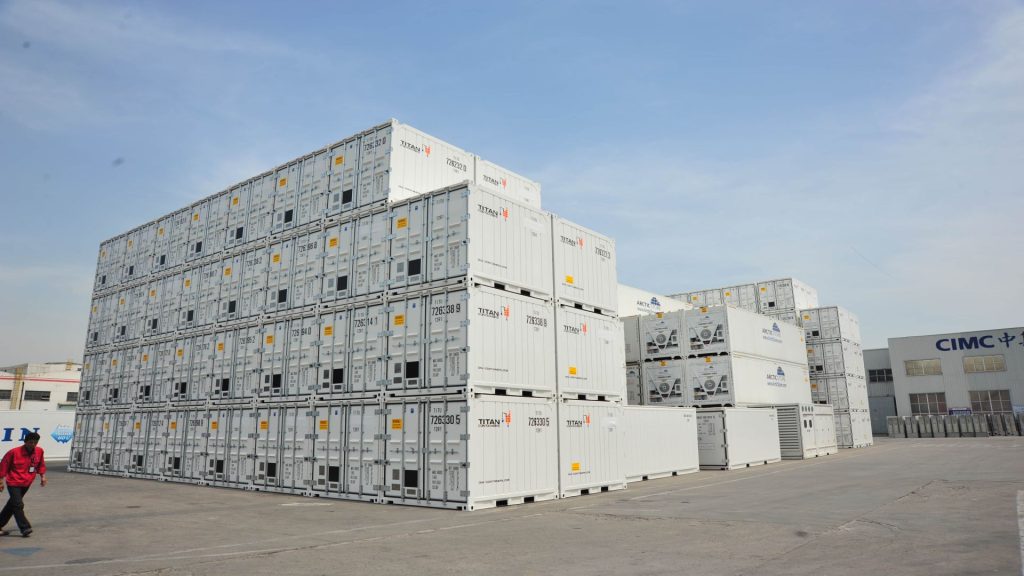


Tricon is a multi-purpose mini combinable container that is widely used today. It is a combination of three single boxes with a dedicated locking device, the combined length and the position of the lifting holes at both ends are exactly the same as the 20-foot standard box. The triptych offers the advantage of independent loading, equivalent to a 20-foot TEU that is easier to load and unload and is suitable for the transport and storage of materiel, and its unique versatility provides an ideal new model for the transport of materiel.
Tricon can play an important role in remote locations where infrastructure is lacking and can be used to support troop systems in combination with the peaceful and wartime logistics environment and the condition of transport equipment.
In the case of poor road conditions and lack of operational equipment, they can be split into single boxes for individual transport using a force utility vehicle.
The choice of Tricon for transporting non-weapon ammunition materials can also achieve camouflage and concealment functions, enhancing the security and confidentiality of materials.
CIMC TLC|RYC Tricon Introduction
- Individual 6’ containers and 3 containers can be connected as 20’ containers for shipment
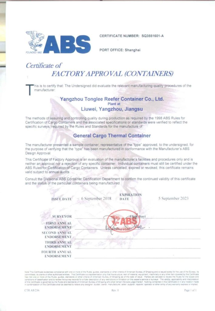
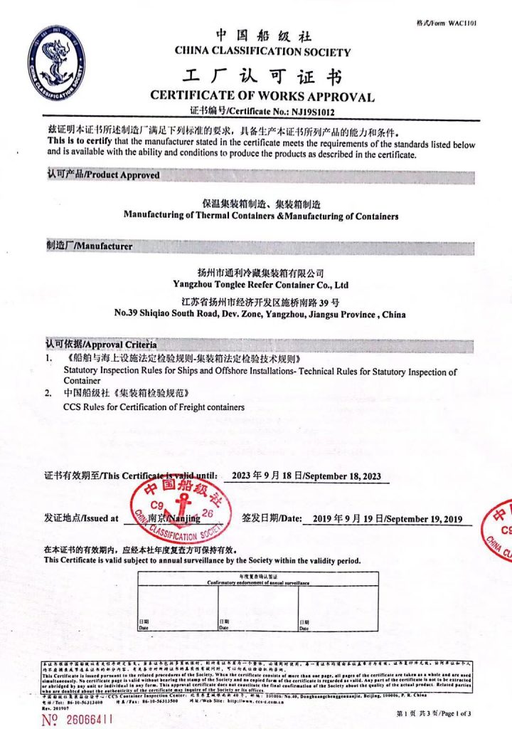
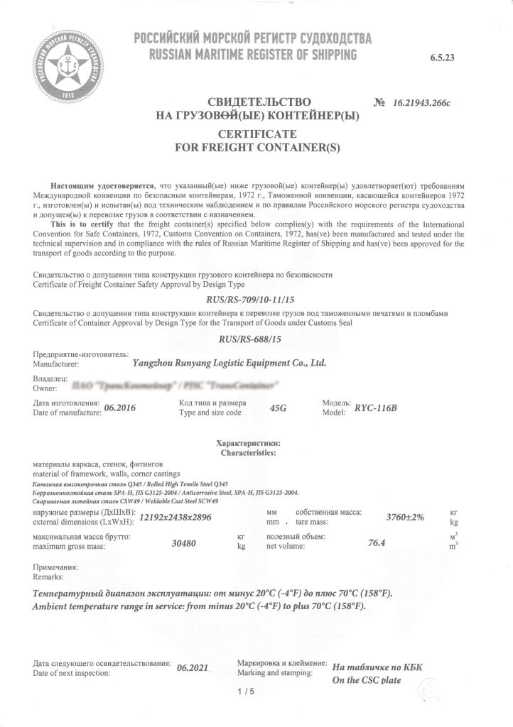
- Full sets certificate available if connected to 20’ size.


Tricon Structural Features
CIMC TLC|RYC Tricon single box makes it easy to quickly load and unload materials, after the combination of the single box can still open and close the door and load and unload goods, greatly improving transport efficiency;
Wall panels and door panels adopt shallow waveforms with wave depth to increase the space in the box;
Each single box is provided with 2 pairs of horizontal and longitudinal cross-arranged fork grooves, a convenient forklift;
Single boxes can be freely combined and split, in the logistics distribution process, the operating unit can be reduced to 1/3 or 1/4 of the 20-foot standard box, more flexible and convenient to use;
The same type of box can withstand an empty box with a 7-layer stack height.
Tricon’s single box is connected by a connector.
Coupler simple structure, convenient operation, fast, with interchangeability. Each single box is equipped with 4 pieces of connectors and a storage box for storing the connectors.
Tricon Data Sheet
| External Size | 1968(L) x 2438(W) x 2438(H) mm |
| Internal Size | 1882(L) x 2288(W) x 2185(H) mm |
| Rear Door Opening | 1870(W) x 2080(H) |
| Internal Cubic Capacity | 9.7 CU.M |
| Maximum Gross Weight | 6760 KGS |
| Tare Weight | 1180 KGS |
| Maximum Payload | 5580 KGS |
| Stacking Test Load ( Per Post) | 86400 KGS |
Tricon Combination Operations ( twist lock connector)
Turn the two handles of the connector to the same direction, and make the connector lock and the connector flange in the same direction, insert one end of the connector lock and flange into one of the single box corner end holes, and then rotate the corresponding handle to lock on the single box;
Use a forklift to move the other single box appropriately, adjust the position and direction of the corner end hole of the other single box relative to the lock at the other end of the connector, insert the lock and flange into the corner end hole;
Push the single box by the forklift, rotate the long handle and lock, you can complete the connection of two single boxes.
Detailed Construction Specifications for Containers
(including Tricon Dry Containers)
1. General
- The container will be constructed with steel frames, fully vertical-corrugated steel sides and front wall, horizontal-corrugated steel double doors at the rear end, die-stamped steel roof and corner fittings.
- All welds of the exterior including the base frames will be continuously welded using CO2 gas.
- Interior welds – when needed – will be stitched with a minimum length of 15 mm.
- Gaps between adjacent components to be welded will not exceed 3 m m or the thickness of the parts being welded.
- Chloroprene sealant is to be applied at the periphery of a floor surface and inside unwelded seams, butyl sealant is used to caulk at the invisible seam of the floor joint area and between the door gasket and frame.
- The internal bend radii of pressed sections of steel will be not less than 1.5 times the thickness of the materials being pressed.
- The wooden floor will be fixed to the base frames by zinc-plated self-tapping screws.
2. Protrusion
- The plane formed by the lower faces of all transverse members shall be positioned by 12.5 mm + +5/-1.5 mm above the plane formed by the lower faces of the bottom corner fittings.
- The top corner fittings are to protrude 6 mm above the highest point of the roof.
- The outside faces of the corner fittings will protrude from the outside faces of the corner posts by a nominal 4 mm for the front and a nominal 3 mm for the rear.
- The outside faces of the corner fittings will protrude from the outside faces of the sides and front wall by a nominal 8 mm.
- Under maximum payload, no part of the container will protrude below the plane formed by the lower faces of the bottom corner fittings at the time of maximum deflection.
- Under 1.8 x maximum gross weight, no part of the container will protrude more than 6.0 mm below the plane formed by the lower faces of the bottom corner fittings at the time of maximum deflection.
3. Corner fittings
The corner fittings will be designed in accordance with ISO 1161 and manufactured at the works approved by the classification society.
4. Base frame structure
The base frame will be composed of two bottom side rails, eighteen cross members, and forklift pockets
- Bottom side rail
Each bottom side rail is built of a 155x52x30x28x4.5 m m thick cold form ed double “Z” section steel made in one piece.
The lower flange of the bottom side rail is outward so as to facilitate easy removal of the cross members during repair and of less susceptible corrosion.
Reinforcement plates to be made of 4.0 mm thick flat steel are welded to the bottom corner fitting. - 4Cross member
The cross members are made of pressed channel section steel with a dimension of 45x122x45x3.5 mm for the normal areas and 75x122x45x4.0 m m for the floor butt joints. The large one is reinforced by three 4.0 mm thick gussets.
The cross members are placed fully to withstand floor strength and welded to each bottom side rail. - Forklift pockets
Each forklift pocket is built of a 3.0 mm thick full-depth flat steel top plate and two 200 mm deep x 6.0 m m thick flat lower end plates between two channel section cross members.
The one set of forklift pockets is designed in accordance with ISO requirements.