


 RU
 EN
Краткий ответ
Providing a power supply for a container, whether for a mobile office, field laboratory, telecommunications shelter, or industrial control room, requires a structured approach to electrical design, distribution, and safety compliance.
According to the IEEE Std 1100-2005 (Emerald Book), Recommended Practice for Powering and Grounding Electronic Equipment, as well as the International Electrotechnical Commission’s (IEC) IEC 60439 series on low-voltage switchgear and controlgear assemblies, state that containerised power systems must integrate external supply interfaces, internal distribution boards, grounding systems, and load-specific protection devices to meet operational performance and personnel safety requirements. This guide covers all aspects of these systems, from grid connection and generator input to internal wiring, uninterruptible power supply (UPS) integration, and off-grid solar-hybrid options, as used in real industrial container projects worldwide.
Understanding the Power Container Concept
In industrial and infrastructure terms, a power container refers to either a standard ISO shipping container (20 or 40 feet) that has been converted into a self-contained electrical power unit, or a purpose-built containerised enclosure that houses power distribution, generation or conditioning equipment. This term encompasses a wide range of applications, including diesel generator sets housed in acoustic enclosures, containerised battery energy storage systems (BESS), mobile substations, prefabricated data centre power modules and electrified site offices for use in remote construction or mining environments. The fundamental engineering challenge underlying all of these is how to reliably, safely and efficiently get electrical power into, through and out of a metal box that may be deployed in a remote field, on a rooftop, in a maritime environment or at a disaster recovery site.
This distinction is important because the answer is not simply ‘run a cable in’. A container presents unique electrical engineering considerations: the steel shell creates a Faraday cage effect that must be managed for grounding and electromagnetic interference (EMI); condensation and thermal cycling mean that all wiring and enclosures must be rated for the internal environment; cable entry points must be weatherproof and mechanically protected; and the entire assembly must comply with the applicable electrical codes of the country of deployment, which may differ substantially from the country of manufacture. Getting all of these factors right from design to commissioning is what transforms a power container from a liability into a functional asset.
External Power Supply Methods: Grid, Generator, and Hybrid
The first engineering decision in any power container project concerns how the unit receives its primary power supply. There are three main types of external supply architecture, each with different connection hardware, protection, and metering requirements.
For containers deployed at semi-permanent or permanent sites with utility grid access, grid connection (shore power/utility feed) is the most cost-effective and operationally straightforward solution. This usually involves a buried or overhead service cable that ends at a weatherproof main incomer, such as a metered distribution board or a moulded case circuit breaker (MCCB), at the exterior cable entry point of the container. The incomer must be rated for the full anticipated load current plus a safety margin (typically 125% of the maximum continuous load, in accordance with NEC Article 220 and IEC 60364 design principles). For three-phase industrial loads, a 400 V/50 Hz or 480 V/60 Hz three-phase four-wire supply is standard, whereas single-phase 230 V/120 V is adequate for light commercial or office containers.
In off-grid deployments, such as remote construction camps, mining sites, disaster relief operations, and military field installations, a diesel or gas generator set provides the primary power supply. Connecting generators to power containers requires a properly rated generator inlet socket (Ceeform or Hubbell-type connectors for portable generators and hardwired bus connections for permanent generators), as well as automatic transfer switching (ATS) if the generator is serving as a backup to a grid feed. There are also harmonic/voltage regulation considerations that are unique to generator sources. Generators produce voltage that fluctuates more than utility power, and their transient behaviour during load steps can cause problems for sensitive electronic equipment inside the container without appropriate conditioning equipment.
Solar-Hybrid and BESS Integration
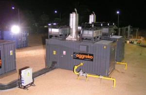
Increasingly, containerised power systems combine solar PV arrays, lithium-ion battery energy storage and either grid or generator backup in a single, integrated architecture. The battery and inverter systems are often housed within the container itself, making the unit both the power source and the distribution point. This configuration is common in telecommunications base stations, remote monitoring installations, and green construction site offices. DC bus voltages for BESS systems range from 48 V (for small systems) to 1,500 V DC (for utility-scale systems), which requires careful separation of AC and DC wiring runs, the use of appropriate DC circuit breakers, and integration of the battery management system (BMS) with the container’s control and monitoring systems.
Internal Electrical Distribution: The Backbone of a Power Container
Once power enters the container, the internal distribution system determines how it is divided, protected, and delivered to individual loads. This is where most of the engineering detail lives, and where specification errors have the most direct impact on operational reliability and safety.
A well-designed power container distribution system follows a hierarchical structure:
Main Incomer | MCCB or ACB | Rated to 125% of full load; with earth fault protection |
Sub-main Distribution | MCB DB or MCC panel | Bus-bar rated, metered per circuit |
Branch Circuits | MCBs / RCBOs | Load-matched; RCBO on all socket/socket-feed circuits |
| Final Outlets | Industrial sockets, terminal blocks | IP44 minimum for interior; IP65 for exposed positions |
| Monitoring | Smart metering / SCADA I/O | Energy logging, remote alarm capability |
Wiring Methods and Cable Routing: Cable selection inside a container must account for the elevated ambient temperatures that can occur when a container is deployed in direct sun (internal air temperatures can reach 55–70°C in tropical environments without active cooling). This typically pushes designers toward cables with 90°C conductor temperature ratings (XLPE or THHN/THWN-2 insulation) rather than standard 70°C PVC types, with current carrying capacity derated per IEC 60364-5-52 tables for actual installation method and grouping. Cable management — cable trays, conduit, or containment systems — must be mechanically fixed to the container’s internal steel structure, with appropriate anti-vibration provisions for mobile or transported containers. All cables passing through the container floor, walls, or roof must use gland plates with IP-rated cable glands to maintain weatherproofing integrity.
Grounding and Bonding: The container’s steel shell must be incorporated into the earthing system, not left floating. A main earth terminal bar (MET) is bonded to the container structure, to the distribution board earth bus, and to an external ground rod or the site earthing grid. For sensitive electronic equipment, a separate clean earth network may be required, per IEEE 1100-2005 recommendations. In generator-supplied systems, the generator neutral-earth bond configuration (solid ground at generator, or separately derived system) must match the distribution system’s earthing arrangement to prevent hazardous neutral-earth voltage differentials.
Power Container Types and Their Specific Requirements
The term “power container” encompasses distinctly different product categories, each with its own electrical architecture. Understanding which category applies to a given project shapes every subsequent design decision.
Containerized Generator Set | On-site power generation | 20 kVA – 3,000 kVA | ATS, acoustic enclosure, fuel system integration |
Mobile Substation Container | Voltage transformation & distribution | 500 kVA – 10 MVA | HV/LV transformer, MV switchgear, SCADA |
| Energy storage & grid support | 250 kWh – 20 MWh | Li-ion battery racks, BMS, PCS inverters | |
| Containerized Data Center | IT compute power distribution | 100 kW – 2 MW (IT load) | PDUs, UPS, precision cooling, remote monitoring |
| Field Office / Site Shelter | Habitable workspace electrification | 10 kVA – 100 kVA | Lighting, HVAC, socket outlets, data/comms |
| Telecom Power Shelter | Base station power supply | 5 kW – 50 kW | Rectifiers, DC distribution, battery backup |
For organizations sourcing these systems at scale — particularly for infrastructure, energy, or industrial projects requiring multiple units with consistent specification across international deployments — the manufacturing standards and systems integration experience of the supplier becomes as important as the electrical specification itself. In our experience working with containerized infrastructure projects, we have found that suppliers like CIMC TLC | RYC | XLC bring both the structural container manufacturing capability and the systems integration expertise to deliver power containers that meet IEC, UL, and project-specific electrical standards without the coordination risk of multi-vendor assembly.
Environmental and Protection Requirements
A power container operating outdoors faces environmental stresses that a fixed building installation does not. The electrical design must explicitly address each of these.
IP Rating and Enclosure Specification: All electrical enclosures, distribution boards, and terminal boxes inside the container should carry a minimum IP43 rating (protected against objects > 1 mm and against water spray up to 60° from vertical). In coastal, high-humidity, or wash-down environments, IP55 or IP65 is appropriate. Cable glands at all wall penetrations must match or exceed the enclosure IP rating.
Temperature Management: As noted above, internal container temperatures in direct sunlight can far exceed the 40°C ambient assumed in standard electrical derating tables. Active cooling — either a dedicated HVAC unit or forced-air ventilation with filtered air intake — is required in most deployments to maintain electrical equipment within its rated temperature range. The HVAC load itself must be included in the total connected load calculation for the incomer sizing.
Corrosion Protection: In marine or coastal deployments, salt-laden air accelerates corrosion on terminal connections, bus bars, and cabinet metalwork. Specifying tinned copper busbars, stainless steel hardware, and conformal coating on PCBs within control components adds cost but avoids the progressive contact resistance increases that cause nuisance tripping and thermal events in poorly specified systems.
EMC and Surge Protection: Steel container enclosures provide some degree of inherent shielding against external electromagnetic interference, but cable entries — particularly for data and control cables — can act as antennas without proper shielding and grounding. Surge protective devices (SPDs) should be installed at the main incomer (Type 1 SPD) and at sensitive equipment distribution points (Type 2 SPD) per IEC 61643-11, especially for generator-supplied or solar-hybrid systems where transient overvoltages are more frequent than on a stiff utility grid.
Commissioning, Testing, and Compliance
No power container should be energized for operational use without a structured commissioning and testing sequence. The minimum testing protocol for a containerized electrical system includes: insulation resistance testing (IR test) of all wiring at 500V DC before first energization; earth continuity verification between the MET and all bonded metalwork; RCD/RCBO trip time testing per IEC 61008/61009 limits; protection relay functional testing (overcurrent, earth fault, under/over voltage); and a full-load operational test documenting voltage levels, current balance across phases, power factor, and temperature rise at key components after one hour of continuous full-load operation.
For systems deployed internationally, applicable codes may include IEC 60364 (most of the world), NEC/NFPA 70 (USA), BS 7671 (UK), or AS/NZS 3000 (Australia/New Zealand). Export documentation — certificates of conformity, test reports, and Bill of Materials with component ratings — should accompany every power container shipped to a regulated market.
FAQ: Power Container Electrical Systems
Q1: What is the most common way to get power into a container on a construction site?
The most common method is a temporary three-phase utility supply from the site distribution board, connected via a weatherproof main incomer socket and MCCB on the container’s exterior. For remote sites without grid access, a diesel generator set — either housed in a separate genset container or positioned nearby — provides the primary supply via a hardwired or plug-connected generator inlet.
Q2: What electrical standards apply to a power container installation?
The applicable standard depends on the deployment country: IEC 60364 governs most international projects, NEC/NFPA 70 applies in the United States, and BS 7671 (18th Edition) applies in the UK. For the container as a manufactured product, IEC 60439 (low-voltage switchgear assemblies) and IEC 61439 (its current replacement series) set the type-testing and verification requirements for the internal distribution assembly.
Q3: How much power can a standard 20 ft or 40 ft container handle?
A 20 ft container used as a field office or telecom shelter typically handles 10–63 kVA of electrical load comfortably within its structural and thermal constraints. A 40 ft container configured as a BESS or mobile substation can house electrical systems ranging from 250 kW to several MW — the limiting factors are thermal management, structural floor loading from heavy equipment, and the external supply capacity available at the deployment site.
Q4: Do I need a UPS in a power container?
A UPS is required whenever the container houses loads that cannot tolerate power interruption — IT equipment, process control systems, telecommunications hardware, or safety-critical monitoring systems. For containers housing only HVAC, lighting, and general socket outlets, a UPS is not typically required, though an automatic transfer switch (ATS) to a backup generator is advisable for any mission-critical application.
Q5: How is the container’s steel shell grounded electrically?
The container’s steel body is connected to the site earthing system via a main earth terminal (MET) bonded to the container structure and connected to a ground rod driven at the installation point, or to the site’s earthing grid. All internal metallic equipment enclosures, cable trays, and structural steelwork are bonded to this MET to create an equipotential zone that eliminates dangerous touch voltages in the event of an insulation fault.
Q6: Can a container be powered entirely by solar with no grid connection?
Yes — a containerized solar-hybrid power system combining rooftop or ground-mounted PV panels, a lithium-ion BESS housed within the container, and a backup generator can provide fully off-grid power for field offices, remote monitoring stations, and telecom shelters. System sizing must account for peak load, daily energy consumption, worst-case solar irradiance for the deployment location, and the number of days of battery autonomy required without solar generation or generator support.
Заключение
The process of supplying power to a container involves a range of engineering disciplines, including electrical system design, materials science, environmental engineering, and regulatory compliance, all within the confined space of an ISO steel box. Every design decision, from the external supply interface and internal distribution hierarchy to grounding, environmental protection, and commissioning testing, has a direct impact on operational reliability, personnel safety, and compliance with international electrical standards. As demand for rapidly deployable, modular infrastructure continues to grow across the energy, telecommunications, construction, and defence sectors, power containers have evolved from jobsite conveniences into sophisticated engineered products. Getting the electrical design right from the outset — and selecting a manufacturing partner with proven systems integration capability — determines whether a power container will perform for its intended service life of 15–25 years or become a costly problem in the field.
Ссылки:
- IEEE Std 1100-2005, “Recommended Practice for Powering and Grounding Electronic Equipment”;
- IEC 60364 series, “Low-Voltage Electrical Installations”;
- IEC 61439 series, “Low-voltage Switchgear and Controlgear Assemblies”;
- IEC 61643-11, “Low-voltage Surge Protective Devices”;
- NFPA 70 / National Electrical Code (NEC), 2023 Edition;
- International Renewable Energy Agency (IRENA), “Battery Storage for Renewables: Market Status and Technology Outlook,” 2023.